GUI
Install and Launch GUI
Follow instructions in software_setup
Top Bar Controls
- Port: Dropdown of available serial ports. Use Refresh to re‑scan if you plug/unplug devices.
- Baud: Serial speed. Default 921600 is typical for fast streaming and our firmware uses the same baudrate as well.
- Connect / Disconnect: Open or close the selected serial port.
- Rate (Hz): How often the GUI streams CTRL_POS frames while you move sliders. Recommended: 50 Hz for smooth motion without saturating USB.
Action Buttons (left→right)
- Homing: Sends opcode
0x01to run the on‑board homing routine. Any Other Input is ignored while homing is active; wait for ACK under a given timeout of 3 minutes. - Set ID: Guided flow to set a servo's bus ID. Requires a single servo connected; the firmware verifies this before writing.
- Trim Servo: Fine‑tune alignment per channel. Enter channel (0–6) and degrees offset (±). The firmware adjusts/persists the channel's
extend_countin NVS so it survives reboots. Use small steps (±5–10°) and test. - Upload Firmware: Flash a
.bindirectly from the GUI. After selection, the board is reset into bootloader, the image is written, and the device restarts. - Set to Extend: Sends a single CTRL_POS frame that sets all channels to 0.000 (fully open / extend posture). Handy as a "panic open".
- GET_POS: Requests positions. Values are shown normalized 0.000 → 1.000, computed from each channel's
extend↔graspcalibration (host 0..65535). - GET_VEL: Requests velocities of the actuator motions.
- GET_CURR: Requests currents in mA, signed — the sign reflects motor direction relative to the channel's servo direction (use magnitude to gauge load).
- GET_TEMP: Requests temperatures (°C) from each servo.
- GET_ALL: Convenience burst that triggers POS + VEL + CURR + TEMP reads in one go and prints results to the log.
- Set Speed: Sets the speed limit for a selected servo ID (opcode
0x31). This sets the maximum speed for that servo; by default, the speed is max and resets after reboot. The speed set here affects the max speed the motor moves during the position control mode, which is different from the speed control mode. - Set Torque: Sets the maximum torque limit for a selected servo ID (opcode
0x32). This limits the maximum torque; by default, torque is max and resets after reboot. The torque set here affects the max torque the motor can apply during the position control mode, which is different from the torque control mode.
Sliders Panel (Center)
Each row controls a single actuator channel with a normalized slider:
- 0.000 → 1.000 maps linearly to the channel’s calibrated extend ↔ grasp range in 2 bytes and sent as 14 bytes payload using CTRL_POS Command.
- While you drag, the GUI streams CTRL_POS frames at the selected Rate (Hz).
- Two small numeric readouts show the current command and (when polled) the latest normalized feedback.
Channel map (top→bottom): thumb_abduction_actuator, thumb_flex_actuator, thumb_tendon_actuator, index_finger_actuator, middle_finger_actuator, ring_finger_actuator, pinky_finger_actuator.
Status & Logs (Bottom)
- Status bar (left): Connection state (e.g., Disconnected, COM12 @ 921600), last error, and homing/flash progress messages.
- RX Log: Text console of responses/telemetry. Useful for debugging, verifying opcodes, and viewing GET_* results.
- Clear Log: Clears the RX Log display (does not affect device state).
Uploading Firmware
To upload firmware to your Aero Hand device:
- Refresh all ports in the GUI to detect connected devices.
- If multiple ports are listed, identify the port for your ESP device:
- On Windows, it is usually a COM port (e.g., COM3, COM12).
- On Linux, look for
/dev/ttyACM0,/dev/ttyACM1, etc.
- Select the correct port and press the Upload Firmware button.
- A dialog box will open—navigate to and select the appropriate firmware
.binfile (firmware_righthand.binorfirmware_lefthand.bin). - The tool will upload the
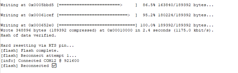
.binfile to the device at offset address 0x10000. - On successful upload, you will see a confirmation message in the GUI.
Notes & Troubleshooting
- If you encounter errors, first check that you have selected the correct COM port.
- The tool uses esptool version 5 or greater. Older versions may not work, as they use
write_flashinstead ofwrite-flash. - After flashing, the tool will attempt to reconnect to the ESP automatically (up to 3 attempts). Usually, it connects on the first try. If not, refresh your ports and try again.
- The firmware is uploaded to offset 0x10000. Do not use merged or partition
.binfiles, as these may cause errors. Only use the provided bin files from theaero-open-firmwarerepository.
Next step is to set the servo IDs, see the next section below.
Setting Servo -IDs
- Power the board with the 6V and connect USB.
- Connect exactly one servo to the bus.
- In the GUI, choose the correct COM Port, press Connect.
- Click Set ID and assign the servo for the channel you’re wiring:
0 → thumb_abduction_actuator1 → thumb_flex_actuator2 → thumb_tendon_actuator3 → index_finger_actuator4 → middle_finger_actuator5 → ring_finger_actuator6 → pinky_finger_actuator
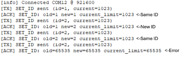
- If the id is successfully set, You will receive an ACK in the RX bar below.
- If you receive 65535 in oldid,new id and current as ACK , It indicates that the id is not successfully set.
- After setting up the ID, you can move the responsible slider to make sure whether the actuator is moving or not.
- Disconnect that servo, plug the next one, and repeat until all seven are assigned.
Notes & Troubleshooting
- Make sure that the board has power and exactly one servo is connected before setting the ID.
- We recommend setting IDs for all servos in sequence (0–6). Any value apart from 0–6 will not be accepted.
- For current limit, we recommend keeping it at the maximum (1023) and pressing OK—do not change this value unless necessary.
- After setting the ID, you will receive the old ID, new ID, and current limit of the servo as confirmation.
- If you receive 65535 in old ID, new ID, and current limit, this indicates that two or more servos are present and the Set ID mode will not proceed.
- Once all IDs are Set, We recommend not to use this function once you are playing and training with the hand.
Trim Servo
When using Trim Servo: First, you will be asked to enter the servo channel (0–6), which represents the sequence: thumb abduction, thumb flexion, thumb tendon, and the four fingers. Next, enter the degrees offset. We recommend making adjustments in steps of 10–20 degrees, then observe the effect using the sliders. If something unusual happens, you may need to perform the homing procedure again to reset the extend count to the baseline.
Left Hand Actuator Table
| Channel | Actuator Name | Extend Count | Grasp Count | Motion (°) | Direction |
|---|---|---|---|---|---|
| 0 | Thumb Abduction | 2048 | 3186 | 100 | +1 |
| 1 | Thumb Flexion | 865 | 2048 | 104 | -1 |
| 2 | Thumb Tendon | 2980 | 0 | 262 | +1 |
| 3 | Index Finger | 817 | 4095 | 288 | -1 |
| 4 | Middle Finger | 817 | 4095 | 288 | -1 |
| 5 | Ring Finger | 817 | 4095 | 288 | -1 |
| 6 | Pinky Finger | 817 | 4095 | 288 | -1 |
Right Hand Actuator Table
| Channel | Actuator Name | Extend Count | Grasp Count | Motion (°) | Direction |
|---|---|---|---|---|---|
| 0 | Thumb Abduction | 2048 | 910 | 100 | -1 |
| 1 | Thumb Flexion | 3231 | 2048 | 104 | +1 |
| 2 | Thumb Tendon | 1115 | 4095 | 262 | -1 |
| 3 | Index Finger | 3278 | 0 | 288 | +1 |
| 4 | Middle Finger | 3278 | 0 | 288 | +1 |
| 5 | Ring Finger | 3278 | 0 | 288 | +1 |
| 6 | Pinky Finger | 3278 | 0 | 288 | +1 |
Motion (°) is calculated as (Grasp Count - Extend Count) / 11.375
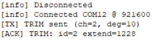
Example: Trimming Right Hand Servo Channel 2 by +10 Degrees
Suppose you set +10 degrees trim for the right hand, servo channel 2 (Thumb Tendon Actuator):
-
Original Extend Count: 1115
-
Grasp Count: 4095
-
Each degree corresponds to 11.375 counts.
-
So, +10 degrees will update Extend Count to:
1115 + (10 × 11.375) = 1228 (rounded to 1228)
-
The new range of motion will be:
4095 - 1228 = 2867 counts
This means the servo will now move through 2867 counts instead of the original 2980 counts which represent 262 degrees of motion and now it will move 252 degrees of total motion only, which will reduce the full range of motion and make it more tight. If you do in the opposite direction , It will increase the motion of servo which will loose the wire and may cause issues. Since , You cannot mofidy the grasp count of the servo, We recommned to go through this table before doing any changes.
Notes & Troubleshooting
- Do not enter values like 360 or -360 degrees, as this may completely change your control direction—please avoid this.
- If the servo becomes too tight, try loosening it by entering degrees in the opposite direction to your last adjustment.
- Use this function only when you want fine control over the servo's range of motion.
- Disconnect power immediately if any actuator moves to an abrupt position and draws stall current (typically 1.3–1.5A).
Tips & Tricks
- Port not listed? Click Refresh; check drivers, cables, and that no other app is holding the port.
- Set‑ID fails? Ensure only one servo is connected and the servo rail is powered.
- No motion? Verify you selected the correct hand build (left/right), try Set to Extend, then move sliders slowly.
- Choppy control? Lower Rate (Hz) or close other serial/USB‑heavy apps.